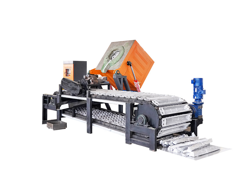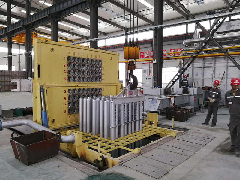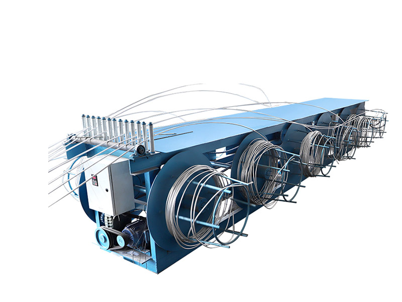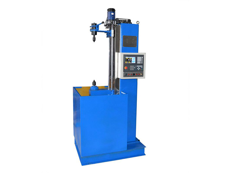
A continuous casting secondary cooling system controls how the strand solidifies after leaving the mold. For equipment buyers and process engineers, nozzle selection alone is not enough: water quality, zone layout, pressure stability, strand support, automation, and maintenance access all affect cooling uniformity. An unsuitable system can produce uneven shell growth and make quality sensitive to casting speed or grade changes. This guide outlines the information needed to specify a practical system for billets, blooms, or slabs without relying on a generic spray arrangement.
Where Secondary Cooling Fits in Continuous Casting
The mold removes heat first and forms the initial solid shell. After the strand exits the mold, the secondary cooling zones continue heat removal while rolls support and guide the partially solidified product. Water-only or air-mist sprays are distributed along the strand according to the required cooling profile.
The design must work as part of the complete caster rather than as an isolated utility. Mold performance, withdrawal speed, steel grade, section size, machine radius, roll pitch, and final solidification position all influence the required zone arrangement.
Start with Product and Process Data
Suppliers need a defined operating envelope. State the cast product type and dimensions, steel grades, target casting-speed range, superheat practice, number of strands, machine geometry, and expected sequence length. Include both normal and transitional conditions such as start-up, grade change, speed reduction, and restart.
Record the available water analysis as well as seasonal supply-temperature variation, pressure limits, and plant return-water constraints. These conditions affect filtration, pumping, heat exchange, corrosion control, and nozzle performance. If the project must reuse an existing water plant, give the supplier measured flow and pressure data instead of only equipment nameplate values.
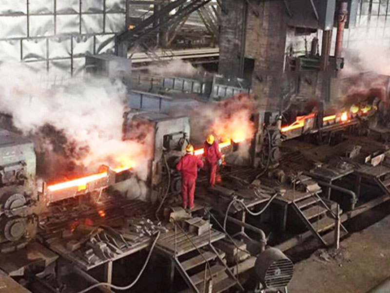
For projects centered on billet production, the cooling study should be coordinated with the steel billet continuous casting production line. This prevents specifications for the spray system, strand support, cutting equipment, and downstream handling from drifting apart.
Divide Cooling into Controllable Zones
Secondary cooling is normally separated into zones so water delivery can follow the changing thermal condition of the strand. Each zone may require different spray density, header arrangement, nozzle pattern, and control range. The objective is gradual, balanced cooling rather than maximum water flow.
- Map each cooling zone to strand position and supporting-roll geometry.
- Define water-flow and pressure ranges for every product family.
- Check overlap between adjacent spray patterns and coverage at edges or corners.
- Provide enough control range for changes in casting speed and section size.
- Identify drainage paths so rebound water does not disturb other zones.
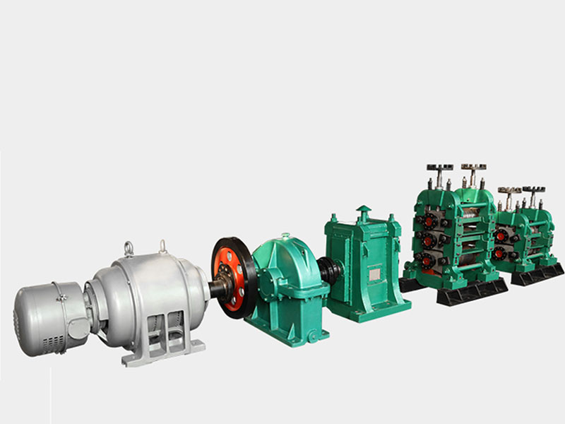
The cooling design should also align with upstream and downstream equipment. Review the wider continuous rolling mill interface when hot charging or direct rolling is part of the production concept.
Select Nozzles, Headers, and Water Services
Nozzle choice depends on the required footprint, flow range, droplet behavior, available pressure, stand-off distance, and risk of blockage. Hydraulic sprays are mechanically simple, while air-mist systems can provide a broad control range where compressed-air quality and operating cost are acceptable.
Headers should be rigid, aligned, protected from impact, and removable for inspection. Piping must maintain stable pressure across operating combinations, and the filtration level should match the smallest nozzle passages. The water system also needs suitable pumps, tanks, heat rejection, make-up control, and monitoring for temperature, pressure, flow, and filter condition.
Ask for a nozzle schedule that identifies type, orientation, flow at stated pressure, zone assignment, and installation position. A documented schedule improves commissioning and prevents incorrect substitutions later. The supplier should also explain the basis for header balancing and how operators can verify distribution after maintenance without exposing personnel to unsafe test conditions.
Integrate Automation and Process Recipes
Zone flow is commonly adjusted using casting speed and a grade- or section-specific recipe. A robust control philosophy explains how commands are calculated, how measured flow is verified, and how the system responds when a valve, pressure transmitter, flowmeter, or communication channel fails.
Operators should see commanded and actual values, alarm limits, active recipe, and equipment availability. Trend data makes it easier to connect surface or internal defects with changes in cooling performance. Access levels and recipe revision control should prevent untracked changes during production.
Plan for Quality, Reliability, and Maintenance
Uneven cooling may be caused by blocked nozzles, misalignment, pressure variation, poor overlap, uncontrolled drainage, or differences between commanded and actual flow. The inspection plan should therefore cover spray-pattern checks, nozzle wear, header alignment, filtration, valve response, sensor calibration, leaks, and scale accumulation.
Maintenance teams need safe access and a practical way to isolate individual circuits. Standardized nozzles and removable headers can reduce repair time, but only when parts identification and orientation are unambiguous. Keep baseline flow and pressure records so gradual deterioration can be detected before it becomes a quality problem.
Use Acceptance Tests that Reflect Production
| Test area | Buyer verification |
|---|---|
| Hydraulics | Pressure stability, zone flow range, leakage, filtration, and pump duty |
| Spray performance | Pattern, overlap, alignment, accessibility, and repeatability |
| Controls | Recipe changes, speed response, alarms, interlocks, trends, and failure modes |
| Documentation | Piping diagrams, nozzle map, settings, spare parts, and maintenance procedures |
| Production | Performance across agreed sections, grades, speeds, and transitional conditions |
Define factory and site acceptance criteria before manufacture. The agreement should state instruments, measurement tolerances, test fluids, operating points, data format, and responsibilities for corrections. Production acceptance should evaluate the complete caster under agreed conditions rather than a single stable recipe.
Use the site’s continuous casting equipment services to coordinate layout, controls, commissioning, and training. For a project-specific proposal, contact the engineering team with product dimensions, grades, casting speeds, water conditions, strand count, and the proposed machine layout.